 |
 |
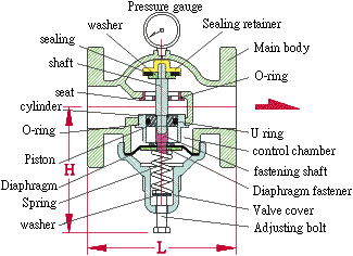
The gate adopts NO design, hence
water supply will not be affected due to instability in inlet
pressure. The internal pressure control chamber adopts diaphragm design, hence the function and life-time will not be affected by water mpurity. Besides, there isl no leakage by this design. When the outlet pressure directly responds to pressure control chamber to adjust setting pressure the response is sensitive and adjustment can be very precise. |
 |
Adjusting range¡G 0.2kgf/cm2 ¡ã4kgf/cm2 3kgf/cm2 ¡ã7kgf/cm2 Test pressure for valve body 21kgf/cm2 Pressure adjusting error +/-0.1kgf/cm2 Applied temperature: -15C to 80C ¢J The pressure gauge indicates the pressure in outlet. | |||||||||||||||||||||||||
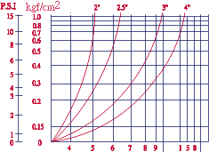
Direct-Activated Pressure Reducing Valve Flow
Chart
1000 2000L/min Flow rater-water |
Q = Rate of flow (GPM) P = Pressure drop across valve (psi) S = Specific gravity of fluid (Water=1) 1 Gallon =3.785 Liter |